
Product feature


Attachment orientation

Main specification
| Heading | Contents | |||||
|---|---|---|---|---|---|---|
| Lead | Ball screw lead (mm) | 20 | 12 | 6 | 3 | |
| Horizontal | Payload | Maximum load capacity (kg) (High-power enabled) | 15 | 29 | 50 | 42 |
| Maximum load capacity (kg) (High-power disabled) | 8 | 14 | 20 | 25 | ||
| Speed/ Acceleration/Deceleration | Maximum speed (mm/s) | 1280 | 900 | 450 | 225 | |
| Minimum speed (mm/s) | 25 | 15 | 8 | 4 | ||
| Rated acceleration/deceleration (G) | 0.3 | 0.1 | 0.1 | 0.3 | ||
| Maximum acceleration/deceleration (G) | 1 | 1 | 1 | 1 | ||
| Vertical | Payload | Maximum load capacity (kg) (High-power enabled) | 1 | 2.5 | 6 | 16 |
| Maximum load capacity (kg) (High-power disabled) | 0.75 | 2 | 5 | 10 | ||
| Speed/ Acceleration/Deceleration | Maximum speed (mm/s) | 1120 | 900 | 450 | 225 | |
| Minimum speed (mm/s) | 25 | 15 | 8 | 4 | ||
| Rated acceleration/deceleration (G) | 0.3 | 0.3 | 0.3 | 0.3 | ||
| Maximum acceleration/deceleration (G) | 0.5 | 0.5 | 0.5 | 0.5 | ||
| Pressing motion | Max. pressing thrust (N) | 67 | 112 | 224 | 449 | |
| Max. pressing speed (mm/s) | 20 | 20 | 20 | 20 | ||
| Cleanroom Compatible | Suction amount (NL/min) | 100 | 70 | 40 | 30 | |
| Brake | Brake specification | Non-excitation electromagnetic brake | ||||
| Brake retention force (kgf) | 1 | 2.5 | 6 | 16 | ||
| Stroke | Minimum stroke (mm) | 50 | 50 | 50 | 50 | |
| Maximum stroke (mm) | 800 | 800 | 800 | 800 | ||
| Stroke pitch (mm) | 50 | 50 | 50 | 50 | ||
| Heading | Contents |
|---|---|
| Drive system | Ball screw φ10mm, rolled C10 |
| Positioning repeatability (Note 3) | ±0.01mm [±0.005mm] |
| Lost motion | 0.1mm or less |
| Base | Material: White alumite treated aluminum |
| Linear guide | Infinite linear circulation type |
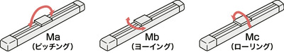
| Allowable static moment value | Ma : 65 N・m |
| Mb : 75 N・m | |
| Mc : 120 N・m | |
| Allowable dynamic moment (Note 4) | Ma : 33.7 N・m |
| Mb : 40.2 N・m | |
| Mc : 55.3 N・m | |
| Cleanliness | Class 2.5 equivalent (ISO 14644-1 standard) |
| Ambient operating temperature and humidity | 0 - 40℃, RH 85% and below (no condensation) |
| Protection grade | IP20 |
| Vibration resistant/Shock resistant | 4.9m/s2 |
| Compatible to overseas standards | CE mark, RoHS compliant |
| Motor type | Pulse motor |
| Encoder type | Battery-less absolute |
| Encoder pulse No. | 8192 pulse/rev |
| Delivery | Written in [Reference for delivery] section of the homepage |
(Note 3) [ ] applies to high precision specification (lead 3, 6 and 12).
(Note 4) Assumes a rated life span of 5,000km. Life time travelling distance differs based on operating condition and attached condition. Please refer to page 1-276 of the general catalogue 2024for the service life.
Slider type moment direction

Stroke and the maximum speed
(Measured in mm/s)
| Lead (mm) | Connecting controller | 50 - 400 (per 50mm) | 450 (mm) | 500 (mm) | 550 (mm) | 600 (mm) | 650 (mm) | 700 (mm) | 750 (mm) | 800 (mm) |
|---|---|---|---|---|---|---|---|---|---|---|
| 20 | High output enabled | 1280 <1120> | 1090 | 940 | 815 | 715 | 630 | 560 | ||
| High Output Disabled | 800 | 715 | 630 | 560 | ||||||
| 12 | High output enabled | 900 | 845 | 705 | 585 | 515 | 445 | 390 | 345 | 315 |
| High Output Disabled | 680<560> | 585<560> | 515 | 445 | 390 | 345 | 315 | |||
| 6 | High output enabled | 450 | 415 | 350 | 295 | 255 | 220 | 190 | 170 | 140 |
| High Output Disabled | 340 | 295 | 255 | 220 | 190 | 170 | 140 | |||
| 3 | High output enabled | 225 | 205 | 170 | 145 | 125 | 110 | 95 | 85 | 70 |
| High Output Disabled | 170 | 145 | 125 | 110 | 95 | 85 | 70 | |||
(Note) < > is applicable when operated vertically.
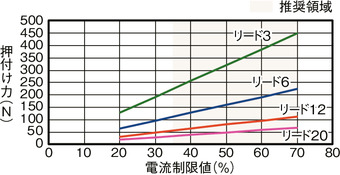
Correlation diagram of push force and current limit value
Payload table by speed/acceleration *High output setting enabled by default. Please refer topage 1-23 of the general catalogue 2024for further details.
High output setting enabled (Power mode) The maximum speed varies depending on the payload. The unit of load capacity is kg. Empty column refers to inoperable motion.
| Orientation | Horizontal | Vertical | ||||||
|---|---|---|---|---|---|---|---|---|
| Speed | Acceleration/Deceleration (G) | |||||||
| (mm/s) | 0.1 | 0.3 | 0.5 | 0.7 | 1 | 0.1 | 0.3 | 0.5 |
| 0 | 15 | 15 | 10 | 8 | 7 | 1 | 1 | 1 |
| 160 | 15 | 15 | 10 | 8 | 7 | 1 | 1 | 1 |
| 320 | 15 | 12 | 10 | 8 | 6 | 1 | 1 | 1 |
| 480 | 12 | 12 | 9 | 8 | 6 | 1 | 1 | 1 |
| 640 | 12 | 12 | 8 | 6 | 5 | 1 | 1 | 1 |
| 800 | 10 | 10 | 6.5 | 4.5 | 3 | 1 | 1 | 1 |
| 960 | 8 | 5 | 3.5 | 1.5 | 1 | 1 | ||
| 1120 | 5 | 3 | 2 | 1 | 0.5 | 0.5 | ||
| 1280 | 1 | 0.5 | ||||||
| Orientation | Horizontal | Vertical | ||||||
|---|---|---|---|---|---|---|---|---|
| Speed | Acceleration/Deceleration (G) | |||||||
| (mm/s) | 0.1 | 0.3 | 0.5 | 0.7 | 1 | 0.1 | 0.3 | 0.5 |
| 0 | 29 | 27 | 20 | 17 | 14 | 2.5 | 2.5 | 2.5 |
| 80 | 29 | 27 | 20 | 17 | 14 | 2.5 | 2.5 | 2.5 |
| 200 | 29 | 27 | 20 | 17 | 14 | 2.5 | 2.5 | 2.5 |
| 320 | 29 | 27 | 20 | 14 | 12 | 2.5 | 2.5 | 2.5 |
| 440 | 29 | 26 | 18 | 12 | 10 | 2.5 | 2.5 | 2.5 |
| 560 | 29 | 20 | 12 | 8 | 7 | 2.5 | 2.5 | 2.5 |
| 700 | 13 | 7 | 5 | 4 | 2 | 1 | ||
| 800 | 8 | 4 | 2 | 1 | 1 | 0.5 | ||
| 900 | 3 | 1 | 0.5 | |||||
| Orientation | Horizontal | Vertical | ||||||
|---|---|---|---|---|---|---|---|---|
| Speed | Acceleration/Deceleration (G) | |||||||
| (mm/s) | 0.1 | 0.3 | 0.5 | 0.7 | 1 | 0.1 | 0.3 | 0.5 |
| 0 | 50 | 45 | 40 | 35 | 30 | 6 | 6 | 6 |
| 40 | 50 | 45 | 40 | 35 | 30 | 6 | 6 | 6 |
| 100 | 50 | 45 | 40 | 35 | 30 | 6 | 6 | 6 |
| 160 | 50 | 43 | 35 | 32 | 20 | 6 | 6 | 6 |
| 220 | 48 | 39 | 29 | 24 | 20 | 6 | 6 | 6 |
| 280 | 44 | 35 | 26 | 21 | 15 | 6 | 6 | 5.5 |
| 340 | 38 | 31 | 19 | 14 | 11 | 6 | 5 | 4.5 |
| 400 | 32 | 18 | 10 | 6 | 4 | 4.5 | 3 | 2.5 |
| 450 | 26 | 10 | 4 | 2 | 1 | 3 | 1.5 | 1 |
| Orientation | Horizontal | Vertical | ||||||
|---|---|---|---|---|---|---|---|---|
| Speed | Acceleration/Deceleration (G) | |||||||
| (mm/s) | 0.1 | 0.3 | 0.5 | 0.7 | 1 | 0.1 | 0.3 | 0.5 |
| 0 | 42 | 42 | 37 | 35 | 35 | 16 | 16 | 16 |
| 50 | 42 | 42 | 37 | 35 | 35 | 16 | 16 | 16 |
| 80 | 40 | 40 | 35 | 35 | 30 | 16 | 16 | 16 |
| 110 | 40 | 40 | 35 | 35 | 30 | 16 | 16 | 16 |
| 140 | 40 | 40 | 35 | 35 | 28 | 16 | 15 | 15 |
| 170 | 40 | 40 | 32 | 26 | 26 | 10 | 10 | 10 |
| 200 | 40 | 30 | 21 | 10 | 10 | 8 | 5 | 5 |
| 225 | 40 | 8 | 5 | 2 | ||||
High output setting disabled (Energy saving mode) The maximum speed varies depending on the payload. The unit of load capacity is kg. Empty column refers to inoperable motion.
| Orientation | Horizontal | Vertical | |
|---|---|---|---|
| Speed | Acceleration/Deceleration (G) | ||
| (mm/s) | 0.3 | 0.7 | 0.3 |
| 0 | 8 | 5 | 0.75 |
| 160 | 8 | 5 | 0.75 |
| 320 | 8 | 5 | 0.75 |
| 480 | 8 | 4 | 0.75 |
| 640 | 6 | 3 | 0.75 |
| 800 | 4 | 1.5 | 0.5 |
| Orientation | Horizontal | Vertical | |
|---|---|---|---|
| Speed | Acceleration/Deceleration (G) | ||
| (mm/s) | 0.3 | 0.7 | 0.3 |
| 0 | 14 | 10 | 2 |
| 80 | 14 | 10 | 2 |
| 200 | 14 | 10 | 2 |
| 320 | 14 | 10 | 2 |
| 440 | 11 | 7 | 1.5 |
| 560 | 7 | 2.5 | 1 |
| 680 | 4 | ||
| Orientation | Horizontal | Vertical | |
|---|---|---|---|
| Speed | Acceleration/Deceleration (G) | ||
| (mm/s) | 0.3 | 0.7 | 0.3 |
| 0 | 20 | 14 | 5 |
| 40 | 20 | 14 | 5 |
| 100 | 20 | 14 | 5 |
| 160 | 20 | 14 | 5 |
| 220 | 16 | 14 | 4 |
| 280 | 13 | 7 | 2.5 |
| 340 | 8 | 1 | 1 |
| Orientation | Horizontal | Vertical | |
|---|---|---|---|
| Speed | Acceleration/Deceleration (G) | ||
| (mm/s) | 0.3 | 0.7 | 0.3 |
| 0 | 25 | 22 | 10 |
| 20 | 25 | 22 | 10 |
| 50 | 25 | 22 | 10 |
| 80 | 25 | 22 | 10 |
| 110 | 20 | 14 | 8 |
| 140 | 15 | 11 | 5 |
| 170 | 5 | 1.5 | |
Adaptive controller
The actuators introduced in this page are controllable using the controllers shown below. Please select their type based on intended usage.
| Name | Appearance | Max. connectable axis No. | Power source voltage | Control method | Maximum positioning points | ||||||||||||||
|---|---|---|---|---|---|---|---|---|---|---|---|---|---|---|---|---|---|---|---|
| Positioner | Pulse train | Program | Network *Select | ||||||||||||||||
| DV | CC | CIE | PR | CN | ML | ML3 | EC | EP | PRT | SSN | ECM | ||||||||
| MSEL-PC/PG | 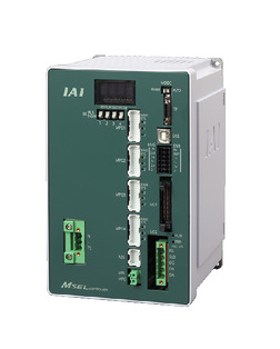 | 4 | Single phase AC 100 - 230V | - | - | ● | ● | ● | - | ● | - | - | - | ● | ● | ● | - | - | 30000 |
| PCON-CB/CGB |  | 1 | DC24V | ● *Selectable | ● *Selectable | - | ● | ● | ● | ● | ● | ● | ● | ● | ● | ● | - | - | 512 (768 for network specification) |
| PCON-CYB/PLB/POB | 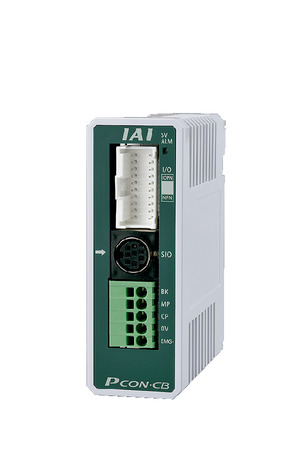 | 1 | ● *Selectable | ● *Selectable | - | - | - | - | - | - | - | - | - | - | - | - | - | 64 | |
| RCON |  | 16 (ML3,SSN,ECM is 8) | - | - | - | ● | ● | ● | ● | - | - | ● | ● | ● | ● | ● | ● | 128 (Position data unavailable for ML3, SSN and ECM) | |
| RSEL | 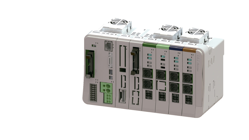 | 8 | - | - | ● | ● | ● | ● | ● | - | - | - | ● | ● | ● | - | - | 36000 | |
(Note) Please refer topage 8-15 of the general catalogue 2024for network abbreviation symbols such as DV, CC and others.
Oversea specification


Important notes on selection
| (1) Maximum speed drops when the stroke length increase, preventing it from reaching the critical revolution value of the ball screws. Use the "Stroke and the maximum speed" to check the maximum speed at the stroke you desire. (2) The load capacity shown in the "Main specification" refers to their maximum value. Please refer to "Load capacity by speed and acceleration table" for further information. (3) Refer "Correlation of pressing force and current limit value" if you may need to operate pressing motion. Pressing force shown are their standard value. For important notes, please refer to page 1-315 of the general catalogue 2024. (4) The duty ratio must be limited according to the ambient temperature of use. Please refer topage 1-326 of the general catalogue 2024for further details. (5) Requires extra care required depending on the mounting posture. Please refer topage 1-307 of the general catalogue 2024for further details. (6) The recommended maximum overhang load length is 300mm or less in the Ma, Mb, and Mc directions (600mm or less for double-slider configurations). Please refer topage 7-72 of the general catalogue 2024for further details on the overhang load length. (7) For the order types and precautions for the double-slider configuration,page 1-293 of the general catalogue 2024. |
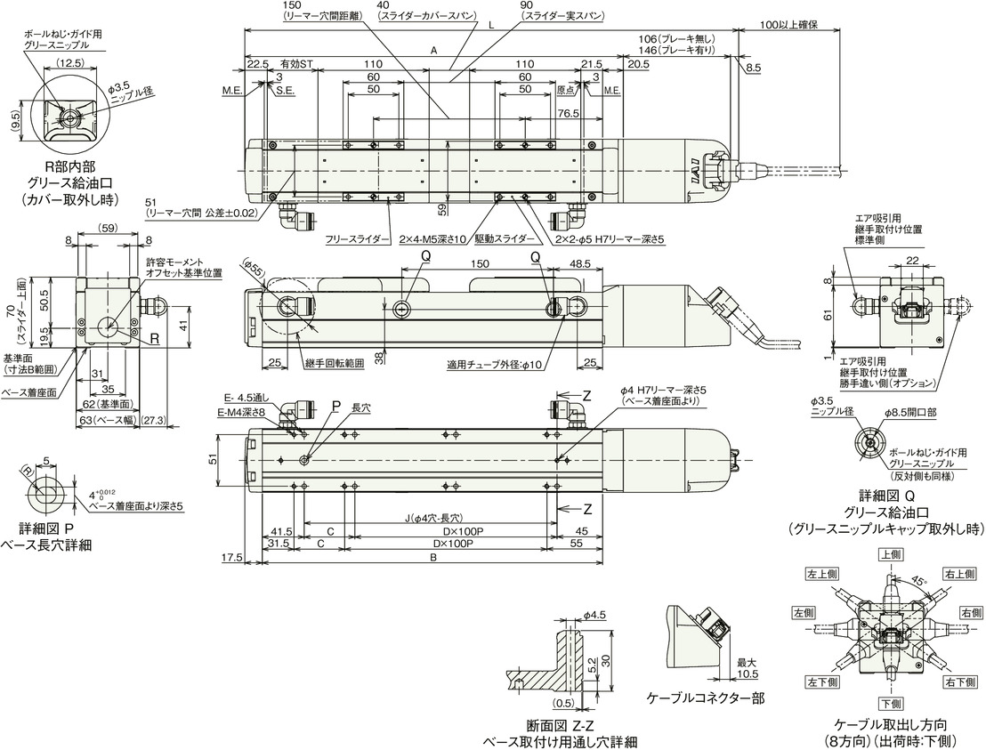
Dimension drawing

ST: Stroke
M.E.: Mechanical end
S.E.: Stroke end
(Note) Please be careful while returning to the home position, for there is a chance of collision while having the slider returning to the M.E. position.
(Note) Please refer topage 3-716 of the general catalogue 2024for precautions when altering the cable exit direction.

Dimension by stroke length
| Stroke | 50 | 100 | 150 | 200 | 250 | 300 | 350 | 400 | 450 | 500 | 550 | 600 | 650 | 700 | 750 | 800 | |
|---|---|---|---|---|---|---|---|---|---|---|---|---|---|---|---|---|---|
| L | Without brake | 339 | 389 | 439 | 489 | 539 | 589 | 639 | 689 | 739 | 789 | 839 | 889 | 939 | 989 | 1039 | 1089 |
| With brake | 379 | 429 | 479 | 529 | 579 | 629 | 679 | 729 | 779 | 829 | 879 | 929 | 979 | 1029 | 1079 | 1129 | |
| A | 224.5 | 274.5 | 324.5 | 374.5 | 424.5 | 474.5 | 524.5 | 574.5 | 624.5 | 674.5 | 724.5 | 774.5 | 824.5 | 874.5 | 924.5 | 974.5 | |
| B | 186.5 | 236.5 | 286.5 | 336.5 | 386.5 | 436.5 | 486.5 | 536.5 | 586.5 | 636.5 | 686.5 | 736.5 | 786.5 | 836.5 | 886.5 | 936.5 | |
| C | 0 | 50 | 0 | 50 | 0 | 50 | 0 | 50 | 0 | 50 | 0 | 50 | 0 | 50 | 0 | 50 | |
| D | 1 | 1 | 2 | 2 | 3 | 3 | 4 | 4 | 5 | 5 | 6 | 6 | 7 | 7 | 8 | 8 | |
| E | 4 | 6 | 6 | 8 | 8 | 10 | 10 | 12 | 12 | 14 | 14 | 16 | 16 | 18 | 18 | 20 | |
| J | 100 | 150 | 200 | 250 | 300 | 350 | 400 | 450 | 500 | 550 | 600 | 650 | 700 | 750 | 800 | 850 | |
Mass by stroke length
| Stroke | 50 | 100 | 150 | 200 | 250 | 300 | 350 | 400 | 450 | 500 | 550 | 600 | 650 | 700 | 750 | 800 | |
|---|---|---|---|---|---|---|---|---|---|---|---|---|---|---|---|---|---|
| Mass (kg) | Without brake | 1.9 | 2.1 | 2.3 | 2.5 | 2.8 | 3.0 | 3.2 | 3.4 | 3.7 | 3.9 | 4.1 | 4.3 | 4.6 | 4.8 | 5.0 | 5.2 |
| With brake | 2.3 | 2.5 | 2.7 | 2.9 | 3.2 | 3.4 | 3.6 | 3.8 | 4.1 | 4.3 | 4.5 | 4.7 | 5.0 | 5.2 | 5.4 | 5.6 | |
Main specification (double slider type)
| Heading | Contents | ||||
|---|---|---|---|---|---|
| Lead | Ball screw lead (mm) | 12 | 6 | 3 | |
| Horizontal | Payload | Maximum load capacity (kg) (High-power enabled) | 24 | 30 | 38 |
| Maximum load capacity (kg) (High-power disabled) | 12 | 18 | 23 | ||
| Speed/ Acceleration/Deceleration | Maximum speed (mm/s) | 700 | 450 | 225 | |
| Minimum speed (mm/s) | 15 | 8 | 4 | ||
| Rated acceleration/deceleration (G) | 0.3 | 0.3 | 0.3 | ||
| Maximum acceleration/deceleration (G) | 1 | 1 | 1 | ||
| Vertical | Payload | Maximum load capacity (kg) (High-power enabled) | - | 4 | 14 |
| Maximum load capacity (kg) (High-power disabled) | - | 3 | 8 | ||
| Speed/ Acceleration/Deceleration | Maximum speed (mm/s) | - | 340 | 200 | |
| Minimum speed (mm/s) | - | 8 | 4 | ||
| Rated acceleration/deceleration (G) | - | 0.3 | 0.3 | ||
| Maximum acceleration/deceleration (G) | - | 0.5 | 0.5 | ||
| Pressing motion | Max. pressing thrust (N) | 112 | 224 | 449 | |
| Max. pressing speed (mm/s) | 20 | 20 | 20 | ||
| Cleanroom Compatible | Suction amount (NL/min) | 100 | 60 | 35 | |
| Brake | Brake specification | Non-excitation electromagnetic brake | |||
| Brake retention force (kgf) | 2.5 | 6 | 16 | ||
| Stroke | Min. nominal stroke (mm) | 200 | 200 | 200 | |
| Min. effective stroke (mm) | 50 | 50 | 50 | ||
| Max. nominal stroke (mm) | 800 | 800 | 800 | ||
| Max. effective stroke (mm) | 650 | 650 | 650 | ||
| Stroke pitch (mm) | 50 | 50 | 50 | ||
(Note) Nominal stroke: Stroke indicated for the model
Effective stroke: Actual stroke during operation
(Note) Lead 12 can't be installed vertically.
| Heading | Contents |
|---|---|
| Drive system | Ball screw φ10mm, rolled C10 |
| Positioning repeatability | ±0.01mm |
| Lost motion | 0.1mm or less |
| Base | Material: White alumite treated aluminum |
| Linear guide | Infinite linear circulation type |
| Allowable static moment value | Ma : 546 N・m |
| Mb : 779 N・m | |
| Mc : 205 N・m | |
| Allowable dynamic moment (Note 5) | Ma : 167 N・m |
| Mb : 199 N・m | |
| Mc : 89.8 N・m | |
| Cleanliness | Class 2.5 equivalent (ISO 14644-1 standard) |
| Ambient operating temperature and humidity | 0 - 40℃, RH 85% and below (no condensation) |
| Protection grade | IP20 |
| Vibration resistant/Shock resistant | 4.9m/s2 |
| Compatible to overseas standards | CE mark, RoHS compliant |
| Motor type | Pulse motor |
| Encoder type | Battery-less absolute |
| Encoder pulse No. | 8192 pulse/rev |
| Delivery | Written in [Reference for delivery] section of the homepage |
(Note 5) Assumes a rated life span of 5,000km. Life time travelling distance differs based on operating condition and attached condition. Please refer to page 1-276 of the general catalogue 2024for the service life.
Slider type moment direction
Payload table by speed/acceleration (double slider type) *High output setting enabled by default. Please refer topage 1-23 of the general catalogue 2024for further details.
High output setting enabled (Power mode) The maximum speed varies depending on the payload. The unit of load capacity is kg. Empty column refers to inoperable motion.
| Orientation | Horizontal | Vertical | ||||
|---|---|---|---|---|---|---|
| Speed | Acceleration/Deceleration (G) | |||||
| (mm/s) | 0.3 | 0.5 | 0.7 | 1 | 0.3 | 0.5 |
| 0 | 24 | 16 | 14 | 12 | ||
| 80 | 24 | 16 | 14 | 12 | ||
| 200 | 24 | 16 | 14 | 12 | ||
| 320 | 24 | 16 | 10 | 8 | ||
| 440 | 20 | 12 | 8 | 6 | ||
| 560 | 12 | 6 | 4 | 2 | ||
| 700 | 5 | 1 | ||||
| Orientation | Horizontal | Vertical | ||||
|---|---|---|---|---|---|---|
| Speed | Acceleration/Deceleration (G) | |||||
| (mm/s) | 0.3 | 0.5 | 0.7 | 1 | 0.3 | 0.5 |
| 0 | 30 | 24 | 22 | 18 | 4 | 4 |
| 40 | 30 | 24 | 22 | 18 | 4 | 4 |
| 100 | 30 | 24 | 22 | 18 | 4 | 4 |
| 160 | 30 | 24 | 22 | 18 | 4 | 4 |
| 220 | 30 | 24 | 20 | 16 | 4 | 4 |
| 280 | 28 | 22 | 18 | 10 | 3 | 3 |
| 340 | 20 | 12 | 10 | 6 | 1 | 1 |
| 400 | 6 | 4 | 1 | |||
| 450 | 1 | |||||
| Orientation | Horizontal | Vertical | ||||
|---|---|---|---|---|---|---|
| Speed | Acceleration/Deceleration (G) | |||||
| (mm/s) | 0.3 | 0.5 | 0.7 | 1 | 0.3 | 0.5 |
| 0 | 38 | 33 | 33 | 33 | 14 | 14 |
| 50 | 38 | 33 | 33 | 33 | 14 | 14 |
| 80 | 38 | 33 | 33 | 28 | 14 | 14 |
| 110 | 38 | 33 | 33 | 28 | 14 | 14 |
| 140 | 38 | 33 | 30 | 26 | 13 | 12 |
| 170 | 36 | 28 | 21 | 20 | 10 | 8 |
| 200 | 25 | 15 | 5 | 4 | 3 | 2 |
| 225 | 3 | |||||
High output setting disabled (Energy saving mode) The maximum speed varies depending on the payload. The unit of load capacity is kg. Empty column refers to inoperable motion.
| Orientation | Horizontal | Vertical | |
|---|---|---|---|
| Speed | Acceleration/Deceleration (G) | ||
| (mm/s) | 0.3 | 0.8 | 0.3 |
| 0 | 12 | 8 | |
| 80 | 12 | 8 | |
| 200 | 12 | 8 | |
| 320 | 12 | 8 | |
| 440 | 9 | 3 | |
| 560 | 2 | ||
| Orientation | Horizontal | Vertical | |
|---|---|---|---|
| Speed | Acceleration/Deceleration (G) | ||
| (mm/s) | 0.3 | 0.8 | 0.3 |
| 0 | 18 | 12 | 3 |
| 40 | 18 | 12 | 3 |
| 100 | 18 | 12 | 3 |
| 160 | 18 | 12 | 3 |
| 220 | 14 | 12 | 2 |
| 280 | 8 | 4 | |
| 340 | 1 | ||
| Orientation | Horizontal | Vertical | |
|---|---|---|---|
| Speed | Acceleration/Deceleration (G) | ||
| (mm/s) | 0.3 | 0.8 | 0.3 |
| 0 | 23 | 20 | 8 |
| 20 | 23 | 20 | 8 |
| 50 | 23 | 20 | 8 |
| 80 | 23 | 20 | 8 |
| 110 | 18 | 12 | 6 |
| 140 | 12 | 8 | 3 |
| 170 | 8 | 4 | 1 |
Stroke and the maximum speed (double slider type)
(Measured in mm/s)
| Lead (mm) | Call stroke | 200 - 400 | 450 | 500 | 550 | 600 | 650 | 700 | 750 | 800 |
|---|---|---|---|---|---|---|---|---|---|---|
| Effective stroke | 50 - 250 | 300 | 350 | 400 | 450 | 500 | 550 | 600 | 650 | |
| Connecting controller | (per 50mm) | (mm) | (mm) | (mm) | (mm) | (mm) | (mm) | (mm) | (mm) | |
| 12 | High output enabled | 700 | 585 | 515 | 445 | 390 | 345 | 315 | ||
| High Output Disabled | 560 | 515 | 445 | 390 | 345 | 315 | ||||
| 6 | High output enabled | 450<340> | 415<340> | 350<340> | 295 | 255 | 220 | 190 | 170 | 140 |
| High Output Disabled | 340<220> | 295<220> | 255<220> | 220 | 190 | 170 | 140 | |||
| 3 | High output enabled | 225<200> | 205<200> | 170 | 145 | 125 | 110 | 95 | 85 | 70 |
| High Output Disabled | 170 | 145 | 125 | 110 | 95 | 85 | 70 | |||
(Note) < > is applicable when operated vertically.
(Note) Nominal stroke: Stroke indicated for the model
Effective stroke: Actual stroke during operation
Dimension drawing (double slider type)
ST: Stroke
M.E.: Mechanical end
S.E.: Stroke end
Drawing (double slider type)
(Note) Please be careful while returning to the home position, for there is a chance of collision while having the slider returning to the M.E. position.
(Note) Please refer topage 3-716 of the general catalogue 2024for precautions when altering the cable exit direction.
Dimension by stroke length
| Call stroke | 200 | 250 | 300 | 350 | 400 | 450 | 500 | 550 | 600 | 650 | 700 | 750 | 800 | |
|---|---|---|---|---|---|---|---|---|---|---|---|---|---|---|
| Effective stroke | 50 | 100 | 150 | 200 | 250 | 300 | 350 | 400 | 450 | 500 | 550 | 600 | 650 | |
| L | Without brake | 489 | 539 | 589 | 639 | 689 | 739 | 789 | 839 | 889 | 939 | 989 | 1039 | 1089 |
| With brake | 529 | 579 | 629 | 679 | 729 | 779 | 829 | 879 | 929 | 979 | 1029 | 1079 | 1129 | |
| A | 374.5 | 424.5 | 474.5 | 524.5 | 574.5 | 624.5 | 674.5 | 724.5 | 774.5 | 824.5 | 874.5 | 924.5 | 974.5 | |
| B | 336.5 | 386.5 | 436.5 | 486.5 | 536.5 | 586.5 | 636.5 | 686.5 | 736.5 | 786.5 | 836.5 | 886.5 | 936.5 | |
| C | 50 | 0 | 50 | 0 | 50 | 0 | 50 | 0 | 50 | 0 | 50 | 0 | 50 | |
| D | 2 | 3 | 3 | 4 | 4 | 5 | 5 | 6 | 6 | 7 | 7 | 8 | 8 | |
| E | 8 | 8 | 10 | 10 | 12 | 12 | 14 | 14 | 16 | 16 | 18 | 18 | 20 | |
| J | 250 | 300 | 350 | 400 | 450 | 500 | 550 | 600 | 650 | 700 | 750 | 800 | 850 | |
(Note) Nominal stroke: Stroke indicated for the model
Effective stroke: Actual stroke during operation
Mass by stroke length
| Call stroke | 200 | 250 | 300 | 350 | 400 | 450 | 500 | 550 | 600 | 650 | 700 | 750 | 800 | |
|---|---|---|---|---|---|---|---|---|---|---|---|---|---|---|
| Effective stroke | 50 | 100 | 150 | 200 | 250 | 300 | 350 | 400 | 450 | 500 | 550 | 600 | 650 | |
| Mass (kg) | Without brake | 2.93 | 3.23 | 3.43 | 3.63 | 3.83 | 4.13 | 4.33 | 4.53 | 4.73 | 5.03 | 5.23 | 5.43 | 5.63 |
| With brake | 3.33 | 3.63 | 3.83 | 4.03 | 4.23 | 4.53 | 4.73 | 4.93 | 5.13 | 5.43 | 5.63 | 5.83 | 6.03 | |
(Note) The weight includes the free slider of 0.43kg added to the weight of the single-slider configuration.
Correlation diagram of push force and current limit value (double slider type)

(Note) Same value as the single slider type.